
TDR Time Domain Reflectometer
As electronic products move towardsHigh-speed transmission, high-frequency signals, and high-density packagingWith the development of electronic products, impedance control of transmission lines has become a key factor affecting signal integrity. If there are impedance discontinuities in the wires, solder joints, or interfaces within the circuit board or packaging, it may lead to signal reflection, signal distortion, or even system failure.
Time Domain Reflectometry (TDR) is an analytical technique that utilizes the reflection characteristics of electrical signals for impedance measurement and fault location. By inputting high-speed step signals into the transmission line and analyzing the reflected signal waveforms, it can accurately determine the location and extent of impedance changes within the transmission line. TDR technology is widely used in PCB transmission line impedance measurement, IC packaging signal integrity analysis, high-speed communication module testing, and fault location of wires and interconnection structures.
When an electrical signal propagates along a transmission line, if there is a change in impedance in the transmission path, such as an open circuit, short circuit, or material discontinuity, part of the signal will be reflected back to the signal source, while another part of the signal continues to propagate forward. Time Domain Reflectometry (TDR) technology utilizes this physical characteristic for measurement. The TDR system sends a fast-rising step voltage signal to the transmission line under test and synchronously measures the voltage changes of the reflected signal. By analyzing the amplitude and time difference of the reflected signal, the impedance distribution in the transmission line can be inferred.
Since the propagation speed of the signal in the transmission line is a known value, the time taken for the reflected signal to return can be used to calculate the defect distance. TDR can not only determine whether there is an impedance anomaly but also accurately locate the defect position, analyzing issues such as transmission line impedance mismatch, PCB trace open circuits or short circuits, packaging interconnection structure anomalies, and high-speed signal channel distortion.
-
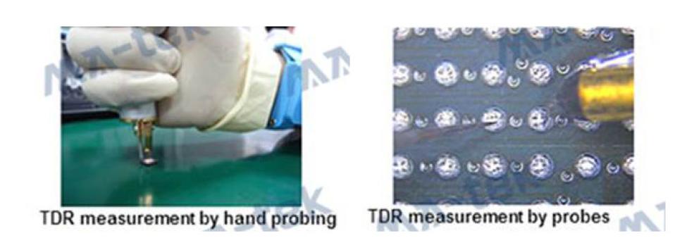
The DR measurement is completed by contacting the probe with the test point. For PCB or module products, the probe can be directly used to contact the test point for measurement; for microelectronics or packaging structures, a micro-probe system can be used for fine signal testing.
-
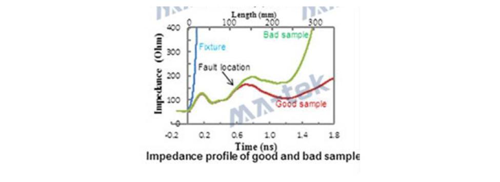
The TDR measurement results are presented in the form of an impedance curve. An ideal transmission line should maintain a stable and smooth impedance curve; if the curve shows significant changes, it indicates that there may be structural anomalies or material discontinuities in the transmission line. This can be used to determine changes in transmission line impedance, signal reflection intensity, and quality differences among different samples.
TDR is usually used in conjunction with other non-destructive testing techniques,such as Scanning Acoustic Tomography (SAT) and X-ray microscopy, to perform more accurate fault location analysis.
TDR technology is mainly applied in the quality assessment of high-speed signal transmission and electronic interconnection structures. In PCB and packaging design, signal integrity issues are often related to transmission line impedance control, making TDR an important tool for engineers to evaluate design quality.
- PCB and high-speed circuits:Transmission line impedance measurement, PCB trace defect localization, high-speed signal integrity analysis
- IC packaging and modules:Detection of interconnection structures in packaging substrates, evaluation of Bump or Wire contact quality.
- High-speed communication products:High-speed data transmission channel analysis, SerDes and high-speed interface signal evaluation
MA-tekLong-term deep cultivation in the field of semiconductor and electronic materials analysis, establishing a complete electrical analysis and material analysis platform, can provide customers with high-precision and high-efficiency fault location services. The TDR analysis has high-speed signal impedance measurement capabilities, and by analyzing the time difference and amplitude variation of the reflected signals, it tracks the location of impedance anomalies in the transmission line, such asopen circuit,short circuit,impedance mismatch and other issues,Accurately locate defects in PCB and packaging structures, integrate analysis technologies such as SAT, X-ray, and SEM, provide a complete solution from electrical localization to material analysis, and assist customers in quickly identifying product failure causes and optimizing product design.
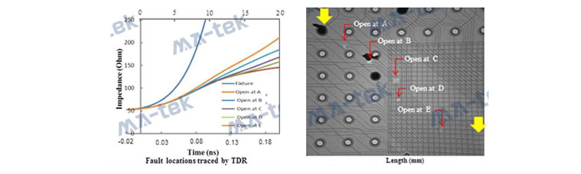
Figure | TDR Fault Location Analysis


