
Board-level temperature cycling test
Board Level Thermal Cycling Test is a method used to evaluateReliability of solder joints for surface mount components (SMT) on printed circuit boards (PCB)An important testing method, the test simulates the thermal stress caused by power on, power off, environmental temperature differences, or power changes in the actual usage environment of electronic products by repeatedly cycling between high and low temperatures, thereby detecting whether the solder joints are due toMismatch of thermal expansion coefficientsAnd gradually produce cracks, fatigue degradation, or eventual failure. Under temperature cycling conditions, the component body, solder, and circuit board materials will experience repeated thermal expansion and contraction, causing the solder joints to endure periodic tensile and shear stresses, which is the most typical induced mechanism of thermal fatigue failure of board-level solder joints.
The board-level temperature cycling test is a focus onsolder joint thermal fatigue lifeThe key reliability test can truly reflect the reliability performance of PCBA in long-term temperature variation environments. MA-tek follows IPC international standards, combining precise temperature control systems and real-time electrical monitoring technology to assist customers in grasping the risk of solder joint degradation during product design and mass production stages, thereby comprehensively enhancing the reliability and quality of electronic products.
The main purpose of the board-level temperature cycling test is to:
-
Evaluate the thermal fatigue life of SMT solder joints under long-term temperature cycling.
-
Analyze the degradation behavior of solder materials under elastic and plastic strain.
-
Comparing the reliability differences of different solder alloys, packaging forms, and PCB designs.
-
As an important basis for product design, material selection, and process optimization.
This test is particularly suitable for automotive electronics, industrial control equipment, communication products, and high-reliability consumer electronics.
Board-level temperature cycling tests are usually based onIPC-9701 (Performance Test Methods and Qualification Requirements for SMT Solder Attachments)The specifications are implemented to ensure consistency in test conditions and failure criteria, as well as industry comparability.
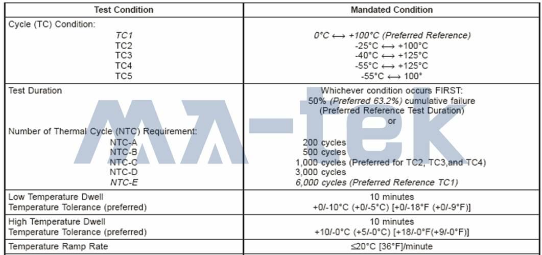
Figure | Typical test conditions and cycle settings for board-level temperature cycling tests (according to IPC-9701 specifications)
The conditions of the temperature cycling test will be selected based on application requirements and specifications, with different high and low temperature combinations and cycle counts. Common settings include:
-
Temperature range: 0°C ↔ +100°C, -40°C ↔ +125°C, -55°C ↔ +125°C, etc.
-
High and low temperature dwell time: usually 10 minutes
-
Temperature change rate (Ramp Rate): generally not exceeding 20°C/min
-
Number of Thermal Cycles: 200, 500, 1,000, 3,000 or 6,000 cycles (selected based on test purpose)
The selection of temperature conditions and the number of cycles directly affects the accumulated thermal strain energy experienced by the solder joints, which is a key factor in life assessment.
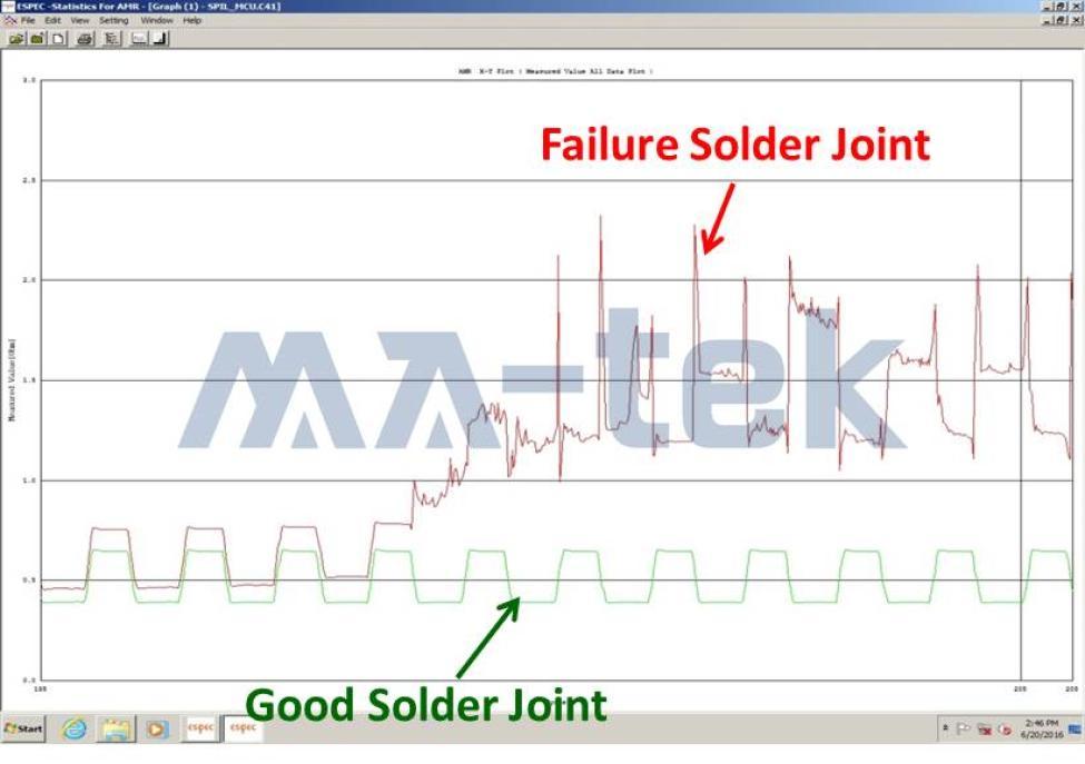
Board-level temperature cycling tests are usually combined withReal-time resistance monitoring system (Daisy Chain Monitoring)During the entire testing process, the solder joint resistance changes are continuously measured to detect whether the solder joint has abnormal conduction due to crack propagation.
Failure Determination Criteria
According to IPC-9701 standards, when the resistance value of the solder jointA 20% increase compared to the initial value.it can be determined that the solder joint has failed.
This method can effectively distinguish:
-
Stable conduction behavior of solder joints with complete structure
-
Crack growth and intermittent failure caused by thermal fatigue
and can clearly reflect the process of solder joints gradually transitioning from a "healthy state" to a "failed state."
Board-level temperature cycling tests are widely applied to:
-
Comparison of thermal fatigue life of solder alloys (such as SnAgCu)
-
Reliability assessment of solder joints for packages such as BGA, CSP, and QFN.
-
Reliability analysis of different PCB thicknesses, layers, and structural designs
-
Optimization of process conditions, reflow curve, and material selection
-
Board-level verification requirements for automotive and high-reliability products
-
Lead-free low-temperature solder paste (usually forSnBiAlloy) thermal fatigue life verification
Through long-term temperature cycling and real-time electrical monitoring, potential solder joint risks can be effectively revealed before product mass production.


