
Board-level cyclic bending test
Board Level Cyclic Bend Test is a method used to evaluateFatigue life and reliability of solder joints of surface-mounted components under repeated bending stress.. It is a mechanical durability test method and belongs to Board-level reliabilityOne of the important items for verification.
In practical applications, electronic products often due tooperational behavior, structural stress or external environmentand bear long-term, low-frequency but repeatedly occurring bending loads, such as mobile phone key operations, laptop opening and closing, automotive module vibrations, and fixed structure deformations, this typeRepeated bendingwill cause the solder joints to gradually accumulate fatigue damage, ultimately leading to crack propagation, instantaneous disconnection, or permanent electrical failure.
The board-level cyclic bending test simulates the aforementioned usage scenario by controlled bending amplitude and cyclic frequency to evaluate the durability of solder joints under long-term fatigue stress.Fatigue life of solder joints under long-term repeated bending stressThe key reliability testing method, MA-tek follows the JEDEC international standards, combining precise bending control and real-time electrical monitoring technology, assisting customers in grasping the fatigue risk of solder joints during product design and mass production stages, comprehensively enhancing the long-term reliability and product quality of PCBA.
The main purposes of the board-level cyclic bending test include:
-
Evaluate the fatigue life of SMT solder joints under repeated bending stress.
-
Analyze the aging behavior and failure modes of solder joints under cyclic bending conditions.
-
Compare the sensitivity of different solder alloys, packaging forms, and PCB structures to fatigue stress.
-
Provide important basis for product structure design, material selection, and reliability verification.
This test is particularly suitable forportable electronics, wearable devices, automotive electronics, and high-reliability modules。
Board Level Cyclic Bend Test is generally based onJEDEC JESD22-B113 (Board Level Cyclic Bend Test Method)The specification execution defines the geometry, cyclic conditions, displacement control methods, and failure criteria for the bending test, ensuring that the test results are consistent and comparable.
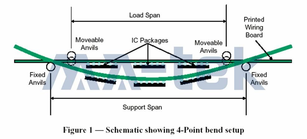
Figure | Board Level Cyclic Bend Test (JESD22-B113) Four-Point Bend Test Configuration Schematic
Test Method | Application of Cyclic Loads under 4-Point Bending Structure
Board Level Cyclic Bend Test is usually adopted4-Point BendStructure. During the test, the circuit board is fixed and supported on both sides (Support Span), and bending loads are applied by two movable force points (Load Span) from above, creating a stable and repeatable bending stress distribution in the central area of the PCB.Displacement control or strain control methodProceed to apply bending deformation repeatedly at a fixed frequency, allowing the solder joints to endure alternating tensile and compressive stresses, gradually accumulating fatigue damage.
Common test conditions are (actual conditions adjusted according to product application and testing purpose):
-
Bending frequency: Approximately1 Hz
-
Bending displacement amplitude: approximately2 mm
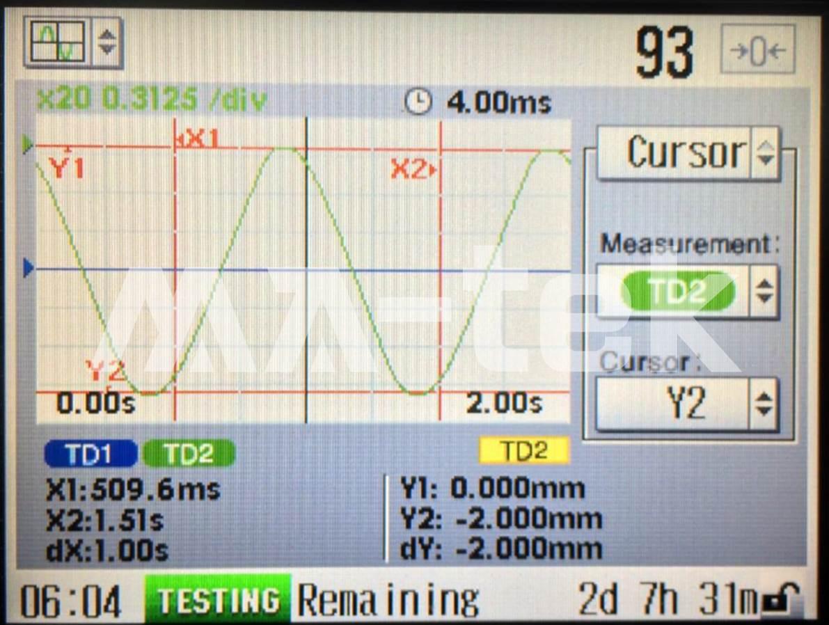
Figure | Real-time resistance measurement curve of solder joints during testing, showing the difference between good solder joints and fatigue failure solder joints.
Real-time monitoring | Electrical measurement of solder joint fatigue degradation
During the entire cyclic bend test process, it is usually accompanied byReal-time Resistance Monitoring System (Multi Event Detector System, MEDS)Continuously measure the changes in solder joint resistance to track the process of solder joints gradually entering fatigue failure from a healthy state. The real-time measurement curve can clearly present:
-
The regular conduction behavior of stable solder joints under cyclic bending.
-
The phenomenon of instant disconnection or sudden resistance increase caused by the generation and expansion of solder joint cracks.
Failure criteria | Definition of electrical failure of solder joints under cyclic bending
The failure criteria for the board level cyclic bend test is usually based on the JESD22-B113 specification, and the determination method is: when the real-time resistance monitoring system detectsThe resistance value exceeds 1000 Ω in a single event., and the event first occurs within 1000 bending cycles, and in the subsequent During the additional 100 cycles, at least 9 occurrences of resistance values greater than 1000 Ω occurred, with each lasting for 1 millisecond (ms) or more.This allows for the determination that the solder joint has experienced fatigue failure. The rigorous determination method can effectively eliminate instantaneous noise interference, ensuring that the failure results reflect the actual fatigue damage of the solder joint.
The practical applications of board-level cyclic bending tests in the industry include:
-
Simulation of pressing and operating behaviors of mobile phones and wearable devices
-
Reliability verification of structures such as laptops and displays subjected to repeated stress.
-
Fatigue assessment of automotive electronic modules in driving and vibration environments
-
Comparison of the durability of solder alloys, packaging structures, and PCB designs
-
Early exposure of fatigue risk in solder joints before mass production


