

What is board-level reliability?
Board-level reliability refers to the verification of the connection reliability of components fixed to the printed circuit board (PCB) after surface mount technology (SMT). The focus of the testing is to evaluate the strength and durability of the solder ball joints between the packaged components and the circuit board, ensuring that the product can maintain stable performance during actual use.
As electronic products develop towards being thinner, smaller, and multifunctional, and as lead-free solder and halogen-free circuit boards gradually replace traditional leaded solder and halogen materials, the overall materials trend towards brittleness, making the reliability of solder joints even more challenging. This is especially true in portable devices, where products are prone to cracking of solder joints when subjected to impacts, drops, or dynamic loads during use or transportation.
In addition, with the advancement of packaging technology, the size of solder joints continues to shrink, making it more difficult to maintain solder joint reliability. These factors make board-level reliability testing (BLR Test) a critical aspect of the electronics industry, receiving significant attention.
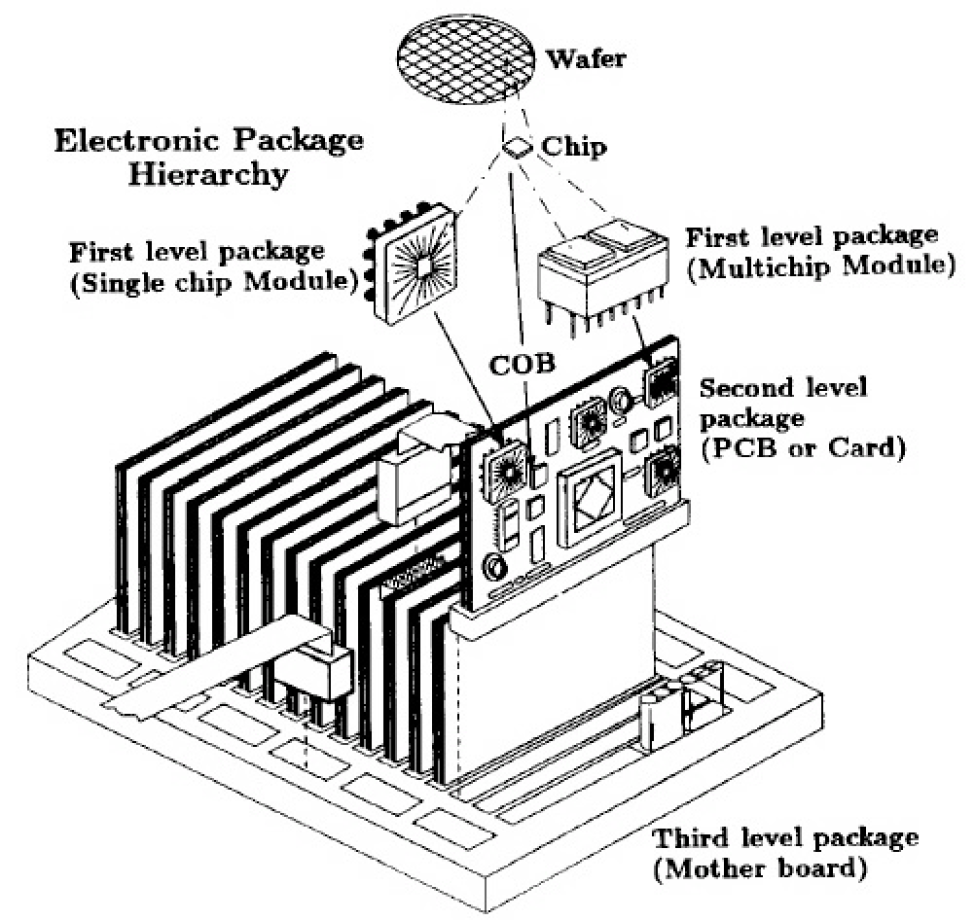
Packaging is a technology based on establishing interconnections between various levels. As shown in the figure, its process technology is divided into five different levels:
- Level Zero (Chip Level Interface Integration): Circuit design and manufacturing on IC chips.
- Level 1 (Single Chip or Multi-Chip Module): The process of packaging IC chips in a case and completing the circuit and sealing protection is also known as Module or Chip-level Packages.
- Second level (Printed Circuit Board, PCB): The process of assembling components that have completed the first level of packaging onto the circuit card.
- Level three (motherboard): The process of combining several circuit boards onto the main board to form a subsystem.
- Level 4 (Electronic Products): The process of combining several subsystems into a complete electronic product (Gate).
Board-level reliability belongs toThe second level of the five levels of electronic packaging technology.The focus is on evaluating the reliability of the combined structure "between the component and the circuit board." According toIPC 9703 standardBoard-level reliability can be further divided into two types:
-
Component board-level testing
-
Using a simplified test board that contains only a single type of component, and testing is conducted according to different groups.
-
The test board may contain multiple identical components, but the design does not need to be the same as the final system circuit board.
-
Suitable for quickly assessing the reliability of component solder joints in the early verification stage.
-
-
System Board Level Testing
-
Use a system board that is close to the actual product, including all major components.
-
The test subjects are actual components in use or equivalent test components.
-
Can more accurately simulate the reliability performance in the final application environment.
-
Daisy Chain Design
In board-level reliability testing, in order to monitor the reliability of all solder joints in the components in real-time, a daisy chain design is often used. The principle is to connect the components and the solder joints on the circuit board into a network structure through special circuit design. Once the product assembly is completed, the testing equipment can determine whether the solder ball joints have failed by detecting the continuity or disconnection status of the network. In other words, regardless of which solder joint develops a crack or breaks, the system can immediately detect the anomaly.
MA-tek has a complete daisy chain test board design service, which can be tailored to customers based on the following international standards: JESD22-B111, JESD22-B111A, JESD22-B113, IPC-9701. Through compliant design and verification, customers can more quickly and accurately grasp the reliability performance of product solder joints, reducing potential failure risks.


