
MST Mechanical Stress Test
MST mechanical stress testing isSimulate the various external force loads that the product may endure during transportation, handling, installation, and actual use.to expose potential structural defects and assembly risks in advance, preventing product failure after market launch or mass production. Common sources of mechanical stress includeDrop, Vibration, Compression, Push / Pull, Mechanical Shock and Bending, etc.When external forces act on the product, its tolerance not only affects the final quality but also directly relates to user experience, brand trust, warranty costs, and after-sales repair rates (RMA).
As electronic products continue to develop towards smaller, thinner, and lighter designs, the bonding area between electronic components and PCBs continues to shrink. Additionally, the fatigue performance of lead-free solder is not as good as that of traditional leaded materials, making the overall structural durability more challenging. Therefore,The verification frequency of various assemblies and component structures has significantly increased, making mechanical stress testing an indispensable reliability confirmation method.By conducting mechanical stress tests on finished or semi-finished products, it is possible to quickly identify:
- weak points in structural design
- Is the assembly quality stable?
- Are there potential risks in the assembly of IC solder joints, BGA, CSP, etc.?
- Will it fail due to transportation vibrations or drops?
Especially for handheld products or mobile device products, the most common failure reason during use isDrop or impactTherefore, the Mechanical Shock Test is usually the most critical verification item in the development process.
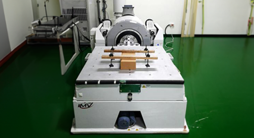
Vibration Test
Products may encounter prolonged shaking, collisions, or shocks during transportation, so vibration tests are one of the most important items in mechanical stress verification, including:
-
Random Vibration:The closest to the real transportation environment, it can verify the structural strength and reliability of the product.
-
Sine Vibration:Used to assess the resonance and fatigue behavior of products at specific frequencies.
When vibration interacts with temperature and humidity, the impact on product durability is greater, thus many industries adoptCombined Stress Teste.g., MIL-HDBKReliability Design ManualIt is pointed out that vibration and temperature are the primary factors causing product failure.ISO 16750 (Automotive Standard)A combined test mode of "temperature cycling + vibration" is also required.
Mechanical Shock Test
Simulating sudden external forces, such as drops and impacts, can quickly expose potential issues with the shell structure, screw fixation, solder joint strength, and more.
Drop Test
The most common reliability tests for handheld devices are used to assess whether the casing cracks, whether the PCBA detaches or deforms, and whether there are hidden cracks in the components such as BGA and CSP after being dropped from different heights.
Combined Stress Test
Applying "vibration + temperature/humidity" simultaneously is closer to real usage environments, simulating scenarios such as automotive electronics operating on bumpy roads and in high-temperature environments, or industrial control equipment functioning on vibrating machines. Such tests can reveal deeper potential risks compared to single stress tests.
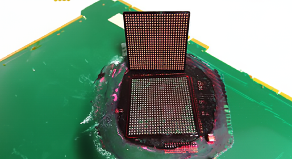
Dye and Pry Test (Dye Penetration Test)
Specifically used to inspect IC solder joints and assembly quality.After completing tests such as vibration, drop, and shock, engineers often need to check whether the solder joints have developed cracks or delaminations due to external forces. At this time, the dye test can be used to penetrate cracks and reveal them after delamination, allowing for a complete observation of the integrity of BGA, CSP, QFN, various assembly solder joints, and PCBA structures. Compared to cross-section analysis, which can only see partial sections, the dye test allows for observation of issues from a "surface" perspective, making it more suitable for rapid reliability assessments of large samples.Compared to cross section, red ink can enlarge defects from "points or lines" to "surfaces", allowing for more accurate identification:
-
BGA / CSP cracks
-
solder ball voids
-
Localized stress issues caused by PCB locking or heat sinks
-
Vibration and Impact
-
Vibration Test
-
Combined Vibration Test
-
Mechanical Shock Test
-
-
Drop and Transportation Simulation
-
Drop Test
-
Tumble Test
-
-
Structural Strength Testing
-
Compression Test
-
Bending Test / Press Test
-
Press Test
-
Torque Test
-
-
Strain and solder joint inspection
-
Strain Measurement
-
Dye and Pry Test
-
Horizontal vibration platform: 60 × 60 cm, 100 × 100 cm
Vertical vibration platform: 60 × 60 cm, 80 × 80 cm
The actual load-bearing size and weight will be evaluated based on the testing conditions and fixture design.


